Tuesday, 6 November 2012

Frequency Division Multiplexing And Wavelength Division Multiplexing

SIMILARITY BETWEEN FDM AND WDM

The term wavelength-division multiplexing is applied to an optical carrier (which is typically described by its wavelength), whereas frequency-division multiplexing applies to a radio carrier (which is more often described by frequency). Since wavelength and frequency are tied together through a simple directly inverse relationship, the two terms actually describe the same concept.

HOW FDM WORKS

At the source end, for each frequency channel, an electronic oscillator generates a carrier signal, a steady oscillating waveform at a single frequency such as a sine wave, that serves to "carry" information. The carrier is much higher in frequency than the data signal. The carrier signal and the incoming data signal (called the baseband signal) are applied to a modulator circuit. The modulator alters some aspect of the carrier signal, such as its amplitude, frequency, or phase, with the data signal, "piggybacking" the data on the carrier. Multiple modulated carriers at different frequencies are sent through the transmission medium, such as a cable or optical fiber.

Thursday, 18 October 2012

OSCILLATOR-PRINCIPLE AND WORKING

An oscillator is an electronic device used for the purpose of generating a signal with constant frequency over a span of time.Every oscillator has at least one active device.This active device acts as an amplifier.
An oscillator starts with noise signal.Whenever we turn ON or turn OFF any electronic device a noise signal is generated,it can never be avoided.This noise acts as feed signal for the oscillator.This signal gets amplified upto a desired level due to the amplifier.
But this noise is available only when the device is turned ON,not after that,thus by rule output should vanish after some time,but this is not the case,output is sustained even after the input is removed.
now let's discuss how it is done:
1) after some propagation some energy is lost,this dampens the signal.
2) in the feedback circuit, the remaining energy is amplified upto the original value and is fed back(in phase) to the incoming signal,hence the signal is preserved.

3) This is done according to BARK HAUSEN CRITERION

 (|βA| ≥ 1)

this product is slightly greater than 1 in order to let the device act as oscillator.
This cycle keeps on repeating and the oscillator circuit continuously generates the signal with a constant frequency.

NEED OF STARTER IN DC MOTORS

Whenever a DC MOTOR starts it requires a current that is equal to 5-6 times its load current to start.Thus it is required to reduce the voltage when the motor starts.This job is done with a starter.In its simplest form, the starter of a dc motor works like a variable resistance in series with the armature circui.Its work is to reduce the starting voltage upto such a value so that the increased current does not burn the armature windings. As the rotating armature of dc motor picks up speed, the starter resistance is gradually reduced to almost zero. At full speed the motor starts running normally, i.e. the job of starter finishes here.
In other words, the starter offers resistance during starting of dc motor only,to provide large current. At full speed,the starter is electrically out of armature circuit of the motor.

Friday, 12 October 2012

Why Amplitude Shift Keying(ASK) is done before transmitting signals through an optical fiber

ASK means converting Digital signal to analog...
ASK scheme is as shown below


Since the transmission of Digital signals is not at all possible due to infinite Bandwidth requirement of digital signals,hence we convert these Digital signals to analog form to make its transmission possible through the optical fiber.
At the receiver end this analog signal is again converted to digital signal for processing at the destination.

Thursday, 11 October 2012

MAXWELL'S CONTRIBUTION IN MAXWELL EQUATION

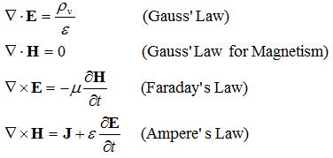
Maxwell's equations are:
 Maxwell's contribution to science in producing these equations lies in the correction he made to Ampère's circuital law.He added the displacement current term to Ampère's circuital law and this enabled him to derive the electromagnetic wave equation.

DISPLACEMENT CURRENT [delta(d)/delta(t)]


This displacement current was the fictitious current flowing in between the 2 plates of a capacitor filled with dielectric(air is also a dielectric) in between.This was a remarkable breakthrough in the communication engineering and made wireless communication possible.All wireless communication systems use dielectric(air) as the medium today to transfer energy from one point to another.Prior to this discovery all conduction was through the conducting medium.

Wednesday, 10 October 2012

bridge rectifier versus center tapped rectifier

Both of them are full wave rectifiers(convert ac to dc)

The bridge rectifier circuit is as shown below
Bridge rectifier


The center tapped rectifier is as shown below
Center tapped full wave rectifier


From the above 2 circuits we can state the differences between the two rectifiers

1)First difference we can see is the number of diodes used
bridge-----4 diodes
center tap-----2 diodes

2)Second difference is that of the transformer used
bridge-----normal transformer
center tap---center tapped transformer

3)Peak inverse voltage(PIV)
peak reverse voltage or peak inverse voltage is the maximum voltage that a diode can withstand in the reverse direction without breaking down or avalanching.
PIV(bridge)---Vm
PIV(center tap)---2Vm

Bridge rectifier is always better than center tapped rectifier due to low peak inverse voltage.

Tuesday, 9 October 2012

Designing subtractor using adder

If we have an adder block and we wish to design a subtractor using this block
Or we can say that if we want an adder to operate like a subtractor, we will have to understand the truth tables and interconversion of both adder as well as subtractor
Truth table of an adder
A    B    sum    carry
0      0      0          0
0      1      1          0
1      0      1          0
1      1      0          1
Truth table of a subtractor
A     B      difference      borrow
0     0             0                       0
0     1             1                       1
1     0             1                       0
1     1             0                       0
From these Truth tables we can see that for inputs A and B ,sum =difference,
and only the carry is to be changed and should be made equal to the borrow  output.
If we xor carry and input B we will get the borrow at the output and our adder will function like a subtractor.
Truth table of xor gate
A     B       output
0     0             0
0     1             1
1     0             1
1     1             0
B (xor) carry =borrow
Truth table is as shown below
B      carry     output
0          0               0
1          0               1
0          0               0
1          1               0
Hence we get the borrow at the output.
Now our adder is ready to work like a subtractor.